Under High Pressure – The Safety, Markings, and Valves of Diving Cylinders
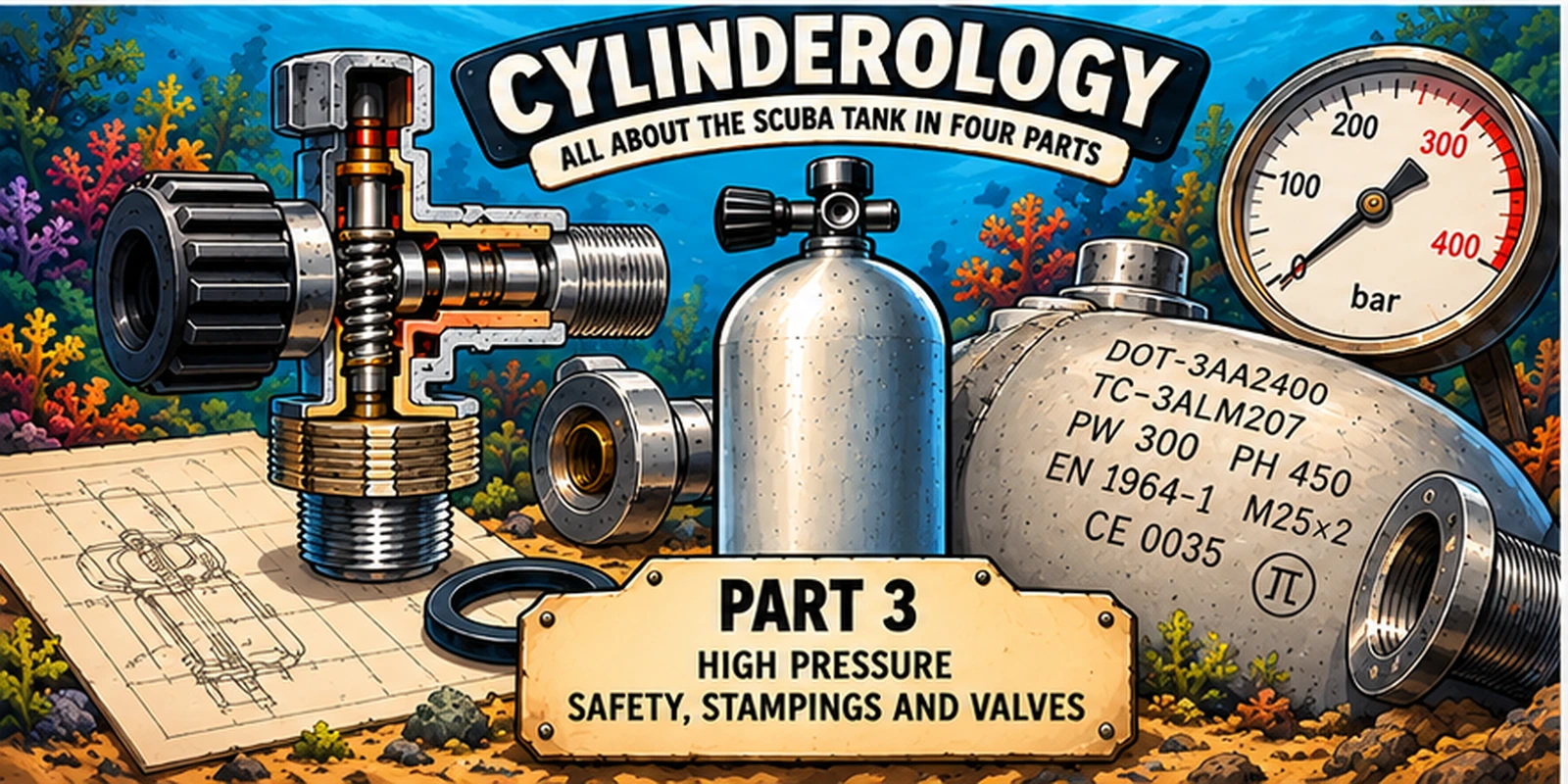
Every diver knows the diving cylinder. It may be the most familiar part of our equipment: a sturdy metal cylinder filled with breathing gas, which we carry on our back and to which we connect our regulator. We know how much air it contains and roughly how long we can dive with it. But how much do we actually know about the cylinder itself? How safe is a diving cylinder that stores air under a pressure of 200 or even 300 bar? What is the difference between working pressure, test pressure, and burst pressure, and what safety margins do manufacturers maintain? What do all those letters, numbers, and symbols on the shoulder of a cylinder mean, and why do some cylinder valves fit one cylinder but not another? In this third part, we examine the technical standards, safety features, and connections that ensure a diving cylinder can be safely filled and used. This is the third part of a four-part series about diving cylinders. Welcome to the third lesson in cylinderology.
1. How Much Pressure Can a Diving Cylinder Actually Withstand?
A standard diving cylinder is filled up to a pressure of 200 or sometimes even 300 bar. Those are impressive pressures, especially when you consider that the air pressure around us at the surface is only about one bar. Yet a diving cylinder is not designed to operate at the limit of its strength at normal working pressure. On the contrary: the construction must provide a sufficient safety margin to allow it to be repeatedly filled, emptied, transported, and used for years. But how much pressure can a diving cylinder actually endure? Why are some cylinders filled up to 300 bar, while others are not allowed to exceed 200 bar? And what happens when that limit is surpassed?
To answer these questions, we must first distinguish between three different pressure concepts: the working pressure, the test pressure, and the burst pressure. They are all expressed in bar or psi but each tells something different about the properties and safety of a cylinder. Especially for diving professionals, it is important not to confuse these terms. The pressure a cylinder must withstand during an inspection is not the same as the pressure with which you may fill it daily.
The most important value is the working pressure, known in English as working pressure (WP) or service pressure (SP). This is the nominal pressure for which the cylinder is approved during normal use, usually at a specified reference temperature. A cylinder with a working pressure of 232 bar should not simply be filled up to 300 bar, even if it looks robust enough. The permitted pressure is determined by the design, material, manufacturing method, and the standard under which the cylinder is produced and certified. This working pressure is marked on the shoulder of the cylinder and is one of the first pieces of information that a filling station employee must check.
Besides the working pressure, there is the test pressure, also called proof pressure. The English term "proof pressure" refers to a pressure used to demonstrate that a construction meets certain requirements. During a hydrostatic test, the cylinder is exposed to a controlled pressure significantly higher than its normal working pressure. The word "hydrostatic" comes from Greek: hydōr means water, and statikos refers to balance or rest. In this test, the cylinder is filled with water and pressurized so that its strength and, depending on the inspection method, its deformation behavior can be assessed.
For many European diving cylinders, the test pressure is one and a half times the working pressure. A 200-bar cylinder is tested at 300 bar, a 232-bar cylinder at 348 bar, and a 300-bar cylinder at 450 bar. However, the 1.5 ratio is not a universal rule. The exact test pressure is determined by the applicable construction and inspection regulations and is usually indicated on the cylinder. Therefore, an inspector may not simply derive this value from what is usual for other cylinders.
Different ratios sometimes apply to American diving cylinders. For instance, the American DOT 3AL specification for common aluminum cylinders mandates a hydrostatic test pressure of five thirds of the working pressure, roughly 167%. A typical AL80 with a working pressure of 3,000 psi, about 207 bar, is therefore tested at 5,000 psi, approximately 345 bar. That is significantly higher than the 4,500 psi expected if you would apply the European ratio of one and a half. The same kind of diving cylinder can thus fall under different inspection systems with varying test pressure requirements. This is an important distinction, especially in Curaçao, where European and North American cylinders are used side by side.
One step further is the burst pressure, or burst pressure in English. This is the pressure at which the cylinder finally fails. The English "burst" means to rupture or suddenly tear apart. For a correctly designed and manufactured cylinder, the burst pressure is significantly higher than the working pressure and also above the test pressure. For various common steel and aluminum high-pressure cylinders, the applicable design standards prescribe a minimum burst pressure of approximately 2.4 to 2.5 times the working pressure, although the exact requirement varies by cylinder type and standard.
An American aluminum AL80 with a working pressure of 207 bar (3000 psi), for example, must, according to the usual DOT 3AL requirements, have a burst pressure of at least approximately 517 bar when subjected to a destructive test. For a steel cylinder of 232 bar, a design requirement of 2.4 times the working pressure would amount to approximately 557 bar. These are enormous pressures, but that does not mean that every single cylinder is subjected to such values during production. A burst test is destructive after all: the pressure is gradually increased until the cylinder actually fails. Manufacturers conduct such tests on selected samples to demonstrate that the design and production process meet the prescribed requirements.
It is not only about the pressure at which a cylinder fails but also about the manner in which it happens. A pressure vessel must not only be strong, but also possess sufficient toughness. A tough material can first deform under extreme load and then crack open, whereas a brittle material can suddenly break and form dangerous fragments. The distinction between tough and brittle is important here: a material can have high strength yet exhibit unfavorable fracture behavior. That is why construction standards impose requirements not only for the strength of a cylinder but also for material properties and behavior during destructive tests.
Even during normal use, the material is constantly subjected to variable loads. Each time a dive cylinder is filled, the cylinder expands very slightly. When the pressure decreases again, the material largely springs back to its original shape. This is called elastic deformation. The term elastic is derived via Greek from a word that among other meanings refers to the ability to return or adapt. As long as the load remains within the designed limits, this deformation is normal and expected. But after many filling cycles, repeated loading can contribute to material fatigue, especially when there are already damages, corrosion, or other weak points present.
The concept of material fatigue is somewhat misleading. Metal does not become tired like a person after a long working day. It involves the formation and slow growth of microscopic cracks under the influence of repeated loading. Because of this, a component can eventually fail at a stress significantly lower than the stress the material could withstand under a single load. That is precisely why, when designing dive cylinders, not only the maximum pressure and material thickness are important, but also fatigue resistance, the quality of the manufacturing process, and the condition of the cylinder throughout its lifespan.
When a dive cylinder suddenly fails under high pressure, an enormous amount of energy can be released in a fraction of a second. The compressed air rapidly expands and can cause a powerful shock wave. Depending on how the cylinder fails, metal fragments can be hurled away or the cylinder itself can be propelled with great force. Especially when a valve breaks off, a cylinder can turn into a particularly dangerous projectile. Anyone in the immediate vicinity at that moment risks serious or even fatal injury. A dive cylinder is therefore not dangerous because it contains air, but because of the enormous amount of energy stored in that compressed air.
That also explains why hydrostatic inspections are carried out with water and not with compressed air. Water is, compared to gas, hardly compressible. When a water-filled cylinder cracks during a pressure test, much less stored compression energy is released than if the same cylinder were pressurized with air. This makes a hydrostatic test considerably safer than a comparable pneumatic test. By the way, pneumatic comes from the Greek pneuma, which can mean air, breath, or spirit. The same word is recognized in pneumatics, the technology where compressed air is used to transfer forces and movements.
The fact that a cylinder must withstand a much higher pressure during inspection than its normal working pressure obviously does not mean that this extra pressure is available for daily use. A steel cylinder of 232 bar that is loaded up to 348 bar during a hydrostatic test does not thereby become a 300-bar cylinder. Surviving a crash test does not mean you can confidently park your car hard against a wall either. The test pressure is applied only during a controlled test, under conditions fundamentally different from normal use. The safety margin is intended to cover uncertainties, material stresses, and exceptional circumstances, not to structurally fill more breathing gas into the same cylinder.
Still, some diving communities consciously fill above the nominal working pressure. Especially among technical divers in the United States, the term 'cave fill' exists for this practice. The name originates from the American cave diving world, where some divers fill certain steel cylinders to significantly higher pressures than those for which they are officially certified. For example, a cylinder with a nominal working pressure of 3,000 psi, approximately 207 bar, can be filled up to 4,000 psi, roughly 276 bar. That is an overfill of no less than 33%. The advantage is clear: more breathing gas in the same cylinder, without having to carry extra cylinders. But that advantage comes at the cost of the safety margin and can increase the fatigue loading of the material.
A cave fill is not the same as a normal filling that accounts for the temperature of the cylinder. During filling, the gas heats up due to compression, causing the measured pressure to temporarily be higher than the pressure remaining after cooling. As we saw in part 2, a cylinder that shows 200 bar immediately after filling may have a noticeably lower pressure after cooling. Some filling procedures take this temperature drop into account to ultimately reach the allowed final pressure. But even then, the manufacturer's instructions, applicable standards, and temperature limits must be respected. A temporary exceedance is not automatically permitted just because the pressure will later decrease.
For a professional filling station, the distinction is straightforward but fundamental: the working pressure is the limit that must be respected during normal use, while the test pressure and burst pressure tell something about the safety margins and the structural characteristics of the cylinder. Neither of the higher values is an invitation to fill the cylinder beyond its working pressure. The valve, connections, and other components of the system also must be suitable for the relevant pressure. After all, a diving cylinder and its valve together form one pressure-bearing unit, whose safety depends not only on the strength of the metal cylinder.
How strong a diving cylinder must be exactly, what test pressure is applied, and under what conditions it may be used are laid down in technical standards and certifications. Much of that information is literally stamped on the shoulder of the cylinder. There we find not only the working pressure and test pressure but also the manufacturer, the serial number, the production standard, and the inspection history. For someone who fills or inspects diving cylinders, these markings are indispensable. And that brings us to the next chapter: the secret language of numbers, letters, and quality marks that every diving cylinder carries with it.
2. The Secret Language on the Shoulder of a Diving Cylinder
Anyone who has looked closely at the shoulder of a diving cylinder has probably seen a collection of numbers, letters, symbols, and dates that at first glance seem to have little meaning. Some markings are neatly arranged in a row, others are spread across the metal. Older cylinders often bear various inspection stamps as well, sometimes from decades ago. The owner also often adds their own identifying mark, name, or numbering to easily identify the cylinder. For most recreational divers, these are mysterious codes, but for someone who fills, inspects, or maintains cylinders, they tell an important story.
Every diving cylinder thus carries a kind of technical passport with it. The markings indicate who made the cylinder, according to which standards it was produced, its capacity, what pressure it can withstand, and when it was first tested. Later hydrostatic inspections also leave their traces. These are not decorative inscriptions but data that can be used to determine whether a cylinder is suitable for the intended use. Some cylinders, after thirty years, have so many inspection stamps on their shoulders that hardly any space remains for the next one. A technical passport that by now starts to resemble a complete travel log.
The Manufacturer and the Serial Number
The first data we can recognize are the name or identification code of the manufacturer and the serial number. Well-known names include Luxfer, Catalina, and Faber, but there are many more producers of high-pressure cylinders worldwide. Sometimes the full name appears on the shoulder, sometimes only a registered manufacturer code. In addition, each cylinder has a unique serial number, by which it can be individually identified, even when dozens of visually identical cylinders stand next to each other.
That is more important than it might seem. When a manufacturer discovers a problem with a particular production batch, the serial numbers can determine which cylinders may be affected. Also, during inspections, certifications, and administrative registrations, the serial number forms the connection between the physical cylinder and its technical history. In a professional filling station, it is therefore wise not only to register the cylinder type and working pressure but also the serial number. Especially when a filling station processes hundreds of cylinders belonging to different owners, reliable identification is indispensable.
The word serial number, by the way, refers to a series, a sequence of products manufactured within a production process. The English term "serial number" has the same origin. A serial number is thus not just a random number: it makes an individual product recognizable within a larger production history. For diving cylinders, this is particularly important because two outwardly identical cylinders can have very different ages, inspection histories, or technical backgrounds.
How much water does it hold, and how much pressure is allowed?
On European diving cylinders, the water content is usually indicated in liters, for example V 12.0 L. The letter V refers to the internal volume of the cylinder. This is therefore not the amount of compressed air it can hold, but the volume the cylinder would contain if you filled it completely with water. As we saw in part 2, this is an essential figure for calculating the available gas supply. A cylinder with a water content of 12 liters, at a pressure of 200 bar, contains approximately 2,400 liters of breathing air according to a simple calculation.
In addition, the working pressure is indicated, often with the letters PW or a similar designation. On a European steel cylinder, you might see PW 232 BAR, for example. This means the cylinder is approved for a nominal working pressure of 232 bar. The corresponding test pressure is often indicated with PH, for example PH 348 BAR. The exact letters and the way the information is displayed can differ per production standard and manufacturer. As we discussed in the previous chapter, working pressure and test pressure are two different values with very different functions.
The markings on American diving cylinders look different. For example, you might see DOT-3AL 3000, which indicates that it is an aluminum cylinder according to the American DOT 3AL specification, with a working pressure of 3,000 psi, approximately 207 bar. Often, a Canadian marking is also present, for example TC-3ALM 207, indicating that the cylinder also complies with Canadian regulations. The American working pressure is given in psi, while the Canadian marking indicates pressure in bar. A U.S. AL80 cylinder, by the way, is not necessarily marked as AL80 on the shoulder: the commercial model name and the official technical markings are two different matters.
This difference is important for diving professionals. A cylinder commonly called an AL80 in everyday language is not automatically suitable to be filled to any arbitrary pressure. The permitted working pressure must be established based on the official markings and applicable regulations. Also, the water content on American DOT cylinders is not always indicated in the same way as on European cylinders. Those used to looking only for a number in liters can easily overlook important information because of this.
The production standard: according to what rules is the cylinder made?
A diving cylinder is not produced just according to the manufacturer's own insights. It must meet technical standards that include, among other things, the choice of material, wall thickness, manufacturing method, strength, testing, and marking. These standards differ per country and per application area, which explains why the shoulders of European and American cylinders can look so different.
The word standard comes via the Latin "norma," which originally referred, among other things, to a carpenter’s square or measuring tool. A standard was literally something by which you could measure whether something was straight and correct. This meaning is still recognizable in modern technology: a technical standard describes the requirements that a product or process must meet. The English word "standard" has a similar function, although historically it refers to a fixed reference point or benchmark.
In the United States, you frequently encounter the designations DOT-3AL for aluminum cylinders and DOT-3AA for steel cylinders. DOT stands for Department of Transportation, the American government agency that among other things sets requirements for portable pressure vessels. In Canada, similar regulations exist under the supervision of Transport Canada, recognized by markings such as TC-3ALM. Some cylinders carry both American and Canadian markings because they are approved for both markets.
For European and internationally certified cylinders, you will see different designations, including standards from the ISO 9809 series for certain steel cylinders and ISO 7866 for seamless aluminum cylinders. ISO stands for International Organization for Standardization, the international organization that develops technical standards. The short name ISO is not simply an abbreviation of the English organization name. It was chosen as an internationally uniform name and is associated with the Greek word isos, meaning 'equal.' That is fitting for an organization that seeks to ensure that the same technical requirements are understood similarly in different parts of the world.
You may also encounter the π symbol on European cylinders, known as the pi marking. This indicates that the portable pressure vessel complies with the applicable European regulations for transportable pressure equipment. The symbol is the same Greek letter pi familiar from mathematics, but here has a very different function. Furthermore, an ISO standard and a European approval mark do not exactly mean the same: the first describes technical product requirements, while the second relates to the assessment of conformity with regulations.
That a cylinder is manufactured according to a recognized standard does not automatically mean it may be filled or used anywhere in the world without further conditions. Applicable legislation, recognition of certification, and validity of inspection also play roles. Especially on an island like Curaçao, where European and American diving cylinders are used side by side, it is important to be able to recognize these different systems. A staff member at a filling station must not only be able to read what is on the cylinder but also understand what that information means regarding whether the cylinder may be filled.
Manufacture Date and Inspection Stamps
One of the most interesting parts of the technical passport is the history of inspections. On American cylinders, the original hydrostatic test date is usually shown as a month and year, for example, 06 21 for June 2021, with the identification mark of the inspection agency between or next to them. At subsequent re-inspections, new dates and inspection marks are added. This way, the shoulder of an older cylinder can slowly change into a small archive of its technical life.
European cylinders also have manufacturing and inspection data applied, but the exact notation and placement may differ. Not every date you find on a cylinder has the same meaning, moreover. The original production date, the first testing, and later periodic re-inspections must be carefully distinguished. Also, an inspection date alone is not sufficient to determine whether a cylinder needs to be re-inspected: you must know which regulations apply to the corresponding cylinder.
In the United States, many common diving cylinders have a hydrostatic re-inspection interval of five years, while various European countries apply different intervals and additional inspection requirements. Therefore, it is unwise to automatically apply one inspection interval to all cylinders. The correct assessment depends on the cylinder, its approval, and the rules under which it is used. Also, a recent hydrostatic test does not mean a cylinder is safe without further control: visible damage, corrosion, or valve problems can be reasons to retire a cylinder earlier.
We encountered the word hydrostatic in the previous chapter. The term inspection (keuring) has a different history: it is related to words that refer to examination, assessment, and making a choice. An inspection is therefore not just an administrative action that adds a new date. It is a technical assessment that determines whether a product still meets the relevant requirements. In part 4, we will look more extensively at what exactly happens during a hydrostatic inspection, how a visual inspection is performed, and why certain cylinders are ultimately rejected.
Empty Weight, Material and Other Indications
Besides the main identification and pressure data, there can be all sorts of other indications on a cylinder. European cylinders often mention an empty weight or tare, usually indicated with T or TW and expressed in kilograms. The word "tara" comes via Italian and Arabic from trade language and refers to the weight of a packaging or container without its contents. In the diving world, it is a useful term because the weight of the empty cylinder partly determines how it behaves underwater.
However, you need to be careful what the manufacturer precisely means by that weight. Depending on the marking and the applicable regulations, the weight of the valve may or may not be included. For an accurate comparison of buoyancy, that difference is important. Moreover, a cylinder with a relatively high empty weight is not automatically more negatively buoyant underwater than a lighter cylinder. As we saw in part 2, buoyancy also depends on the external volume and thus on the amount of water the cylinder displaces.
Some cylinders also state the alloy used, for example 6061 for aluminum cylinders. That can be particularly relevant information. Older aluminum cylinders of certain alloys, including 6351-T6, may be susceptible to a specific form of cracking in the neck called sustained-load cracking. This English term literally means cracking under prolonged stress. For such cylinders, the combination of manufacturer, serial number, production date and material marking can help determine whether additional inspections are necessary. Not every old aluminum cylinder is automatically unsafe, but some production series do require special attention. This topic will also be covered in more detail in part 4.
Not all information is permanently stamped into the metal. Some manufacturers use additional labels, color markings, or printed model data. These can be useful but do not replace the official identification and approval markings. Also, protective nets, tank boots, paint or corrosion can cause certain data to become hard to read. An illegible or unclear marking is no small matter at a filling station: if it cannot be determined with sufficient certainty for which pressure a cylinder is approved, assumptions may not simply be made.
Two Cylinders, Two Different Languages
Place a European steel 12-liter cylinder next to an American aluminum AL80, and you immediately see that they speak different technical languages. On the European cylinder, you usually find the water capacity, working pressure and test pressure in liters and bar. On the American cylinder, the DOT specification, the working pressure in psi, and the approval stamps stand out. Both systems have the same purpose: to make the properties and safety history of the cylinder recognizable and verifiable.
For someone who regularly works with diving cylinders, reading those markings eventually becomes almost automatic. A few numbers and letters are often enough to know what type of cylinder you are dealing with, which pressure corresponds to it, and which data still need to be checked. Nevertheless, it remains important not to rely solely on experience or recognition. A diving professional must actually check the relevant markings, especially when a cylinder deviates from the models they work with daily.
The markings on the shoulder tell us a lot about the cylinder itself, but not everything about the complete system with which we breathe underwater. For that, the cylinder valve is also important. It must not only fit the cylinder but also form a safe connection with the first stage of the regulator. And that brings us to the next chapter: two connections all divers know but whose technical differences are often not well understood. DIN and INT.
3. From Cylinder to Regulator: DIN and INT
A diving cylinder is not much more than a sturdy metal pressure vessel by itself. Only when a valve is mounted on it can we use the compressed air in a controlled way. The cylinder valve makes it possible to open and close the air supply and simultaneously forms the connection to the regulator. It is a relatively simple component with a straightforward task: open or close. Only the valve must work reliably at pressures of 200 to sometimes even 300 bar, and do so for many years under conditions where saltwater, sand, and careless use are constantly a threat.
Not all cylinder valves are the same. Not every valve fits every cylinder, not every regulator fits every valve, and two connectors that look almost identical are not necessarily interchangeable. To understand this, we need to distinguish between two different connections. At the bottom of the valve is the thread by which it is attached to the neck of the diving cylinder. On the other side is the connection to which the first stage of the regulator is mounted. Both connections must withstand the full cylinder pressure, but they use different technical standards. In this chapter, we look at the connection every diver knows. The thread between cylinder and valve will be discussed extensively in the next chapter.
Worldwide, mainly two systems are used to connect a regulator to a diving cylinder: DIN and INT. The acronym DIN refers to the German Deutsches Institut für Normung, the organization that develops technical standards. Historically, DIN was also explained as Deutsche Industrie-Norm, a term you will still come across regularly. INT stands for international, which is somewhat optimistic for a connection that must compete worldwide with DIN. Apparently, international is not the same as universal. In English-speaking countries, the INT connection is usually called yoke or A-clamp.
With an INT connection, the first stage of the regulator is placed over the cylinder valve with a metal bracket. Then a large screw is tightened, which presses the regulator against the valve opening. A small O-ring in the cylinder valve provides the seal between the two parts. The English word yoke literally means 'yoke', an apt name for the clamp that grips around the cylinder valve. The name A-clamp refers to the same construction: a clamp that secures the regulator against the valve. The system is simple and quick to use and therefore still very popular at recreational dive centers, especially in North America and the Caribbean.
With a DIN connection, it works differently. The first stage has a screwable connection that screws directly into the cylinder valve. The O-ring is usually on the regulator's connection and is pressed inside the valve against a sealing surface. As a result, the seal is better protected than with an INT connection, where the O-ring is visible on the outside of the valve. Moreover, the first stage in the DIN system is held directly by a threaded connection, instead of by a clamp that grips around it. As a mnemonic, we sometimes teach our students: 'DIN you screw in.' This may not be the most profound technical explanation, but it helps to distinguish the two systems.
Both connections can function reliably when used correctly. Still, DIN has some practical advantages, especially in technical diving, cave diving, and wreck diving. The connection is more compact, protrudes less, and is therefore less vulnerable when the diver moves through narrow passages or gets entangled with equipment. Also, the O-ring is better protected against damage or the unexpected ejection of the seal. INT, on the other hand, has the advantage that the regulator can be connected and disconnected very easily and quickly, without having to screw the threaded connection multiple turns in or out. This makes INT a practical system, especially in recreational dive centers where students and less experienced divers often assemble and disassemble their equipment themselves.
As if having two different connections were not enough, within the DIN system, there are also versions for different working pressures. The best known are the 200/232-bar and 300-bar versions. The main difference lies in the depth of the connection and the length of the threaded portion. A common 232-bar DIN connection has five threads, while the 300-bar version has seven. The 300-bar connection thus engages deeper into the valve. So, it is not simply the same connection with a different pressure value marked on it, but a deliberately differently designed connection.
That difference is made to prevent a regulator designed only for a lower pressure from being connected to a 300-bar valve. In such a wrong combination, the O-ring does not reach the dedicated sealing surface, so the connection cannot seal properly. If the valve is nevertheless opened, high-pressure air can escape. Usually, a first stage with a 300-bar DIN connection can also be used on a 232-bar DIN valve, provided the other specifications match. Conversely, a 232-bar DIN connection cannot seal properly in a 300-bar DIN valve because the connection does not reach deep enough. The extra length of the 300-bar connection thus acts as a kind of mechanical protection against an unsuitable combination.
INT connections are commonly used for cylinder pressures up to 200 or 232 bar, depending on the design and certification. For 300-bar diving cylinders, DIN is typically used. That does not mean that every DIN regulator is automatically suitable for 300 bar. The pressure rating of the first stage, the connection, and the cylinder valve must match the intended use. The same applies to filling hoses and filling adapters. For a filling station employee, it is therefore important not only to recognize whether a cylinder has DIN or INT but also to determine for which pressure the particular connection is rated.
Some cylinder valves are equipped with a removable insert, allowing the same valve to be used with either a DIN or an INT regulator. Such an insert is often called a DIN-to-INT insert or simply an insert, the English term for something placed inside. When the insert is in place, the valve offers a flat connection onto which an INT regulator with a yoke can be secured. When the insert is removed, the deeper DIN connection becomes available. These types of valves are also known as convertible valves because they can be converted between two connection types.
This is especially handy for dive centers. A guest with a DIN regulator can use the same cylinder as someone with an INT regulator without having to replace the entire cylinder valve. However, not every valve is suitable for such an insert, and using one does not change the maximum allowed pressure rating of the valve or the regulator. An insert does not turn a 232-bar valve into a 300-bar valve. Also, the insert must be of the correct type and used according to the manufacturer's instructions. Two parts that look similar at first glance are not necessarily interchangeable.
Besides these built-in solutions, there are also separate adapters that allow a DIN regulator to connect to an INT valve or an INT regulator to be used on a suitable DIN valve. Such adapters can be useful when a diver travels with their own equipment and arrives at a destination where a different connection system is common. However, they also add extra connections, seals, and sometimes a considerable length to the first stage. This makes the setup less compact and introduces extra potential leakage points. An adapter is therefore primarily a practical solution for a compatibility issue, not automatically an improvement of the original connection.
For dive professionals, recognizing DIN and INT is a basic skill, but it also requires careful inspection of the connection. Before mounting a regulator, one must check if the O-ring is present and in good condition, if the sealing surfaces are clean, and if there are no visible damages to the valve or first stage. For a DIN connection, the thread should smoothly screw in without force. For an INT connection, the yoke must fit correctly over the valve, and the first stage must press neatly against the sealing surface. A connection that does not fit properly should never be forced with extra strength.
Caution is also important when opening the cylinder valve. The regulator must be properly attached, and the pressure should be built up gradually. If a leak occurs, the valve must be closed again and the connection depressurized before investigating the cause. A hissing O-ring is not an invitation to tighten the connection under pressure with extra force. And a damaged thread is definitely not a problem that can be fixed with brute strength. With high-pressure equipment, it is usually wiser to replace a part or have a qualified technician inspect it than to attempt to make a faulty connection usable.
In the end, DIN and INT are two different solutions to the same technical problem: how do we safely and reliably connect a regulator to a cylinder containing thousands of liters of compressed air? Both systems have their own history, advantages, and limitations. For the recreational diver, the most important thing is to recognize the correct connector and mount the equipment correctly. For the diving professional, an additional responsibility is to assess the compatibility, condition, and pressure rating of the connection.
But that's just one side of the cylinder valve. On the other side is a connection that is much less often removed and that most divers have probably never studied up close: the threading by which the valve is attached to the neck of the cylinder. There are also different standards for this, including M25×2, ¾-14 NPSM, and BSPP. Unlike DIN and INT, the differences are sometimes barely recognizable to the naked eye. This is precisely what makes this connection so interesting, and potentially so dangerous. The next chapter is about exactly this.
4. Threading: A Small Difference with Large Consequences
At first glance, a diving cylinder and a cylinder valve seem like two parts that naturally belong together. The valve has a thread at the bottom, the cylinder has an opening with matching threading, and when you screw the valve in, a strong connection is created. It can't be that complicated, right? Unfortunately, reality is somewhat less simple. There are different threading standards that are sometimes barely distinguishable from each other, but certainly not interchangeable. A wrong combination can have catastrophic consequences under pressures of 200 or 300 bar.
For most recreational divers, this is a topic they rarely encounter. After all, the cylinder valve is not removed after every dive but usually remains attached to the cylinder for years. For dive professionals, filling station employees, and technicians who maintain diving cylinders, the situation is different. They must understand why a valve does not simply fit any cylinder, what the various threading markings mean, and why a connection that mechanically seems to fit can still be dangerous. This involves much more than just a few millimeters of difference.
Threading: How Does It Actually Work?
A thread is essentially a spiral ridge that runs around a cylindrical surface. On a bolt, the thread is on the outside, on a nut, on the inside. When both parts are screwed together, the spiral converts a turning motion into movement along the axis. This way, two parts can be firmly connected. The Dutch word "schroefdraad" describes this shape very aptly: a thread that spirals around a screw. The English "thread" literally means thread, while "screw" is historically related to words describing a turning or spiral movement.
On a cylinder valve, the external thread is located on the lower part of the valve, also called the valve stem. The matching internal thread is made in the neck of the cylinder. Together they form a connection that must hold the valve in place, even when the cylinder is under hundreds of bars of pressure. The force with which the compressed air tries to push the valve out is significant. At 200 bar, a force equivalent to approximately 200 kilograms per square centimeter acts. The total force on the valve depends on the surface area on which the pressure acts but can easily reach thousands of kilograms of force.
This means the threading must do much more than just prevent the valve from loosening when someone turns it. It must safely transmit the axial force of the gas pressure to the cylinder neck. The load is distributed over the contact surfaces of the thread turns. How well this load is distributed depends, among other things, on the diameter, thread pitch, thread profile, fit, and quality of installation. A connection can look perfectly normal from the outside yet still lack sufficient strength if one of these properties does not match the design.
Metric and Imperial: Two Ways to Describe the Same Thread
Just as with the volume of diving cylinders and the indication of working pressure, we also encounter two different measurement systems for screw threads. In Europe, many screw threads are designated according to the metric system, with dimensions in millimeters. In North America, many standards are based on inches. Both systems essentially describe the same properties but do so differently.
A common metric neck thread on modern European diving cylinders is M25×2. The letter M stands for metric thread, the number 25 refers to the nominal outer diameter of 25 millimeters, and the number 2 indicates the thread pitch: the distance between two consecutive thread crests is 2 millimeters. When you screw a valve one complete turn on a single-start thread, it advances 2 millimeters along the neck. This is a clear way to describe a thread: diameter and pitch, both in millimeters.
On American aluminum diving cylinders, you often see the designation ¾-14 NPSM. The letters NPSM stand for National Pipe Straight Mechanical, an American standard for parallel pipe threads. The number ¾ refers to the nominal pipe size of three-quarters of an inch, while 14 indicates the thread has 14 threads per inch. One inch is exactly 25.4 millimeters, so the thread pitch is 25.4 divided by 14, or approximately 1.814 millimeters. This is slightly less than the 2 millimeters of M25×2.
An important detail is that the ¾ inch designation here does not mean the actual outer diameter of the thread is exactly 19.05 millimeters. For pipe threads, the nominal inch size historically referred to the dimensions of pipes for which the standard was developed. The actual outer diameter of a ¾-14 NPSM thread is approximately 26.4 millimeters. That is significantly larger than the 25 millimeters of M25×2, while the thread pitch is slightly smaller. Thus, two threads can differ in both diameter and pitch, even if their designations at first glance appear to suggest roughly the same sizes.
In addition to these two standards, there is also ¾-14 BSPP, a British parallel pipe thread. BSPP stands for British Standard Pipe Parallel. Like NPSM, this thread has 14 threads per inch, but the nominal outer diameter is about 26.44 millimeters and the thread profile is different. American NPSM thread uses a thread angle of 60 degrees, whereas the British BSPP standard is based on the Whitworth profile with a thread angle of 55 degrees. The name Whitworth refers to the British engineer Joseph Whitworth, who played an important role in thread standardization in the nineteenth century. His work made it possible to reliably interchange bolts and nuts from different manufacturers, something that was not self-evident before the introduction of uniform standards.
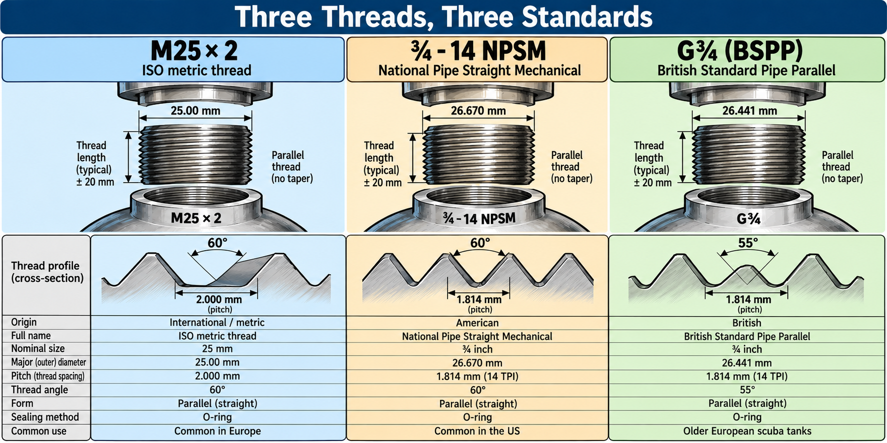
Why Almost Fitting Threads Are Especially Dangerous
A wrong thread connection does not have to immediately seize up. Some thread types look so similar that a valve can be partially, or sometimes surprisingly far, screwed into the neck of a cylinder. This can create the impression that the parts belong together. But when the diameter, pitch, or thread angle does not exactly match, the load is not properly distributed over the thread turns. Instead of an even and predictable connection, only a few threads bear most of the force.
At low pressure, such an error may not immediately be visible. A valve might even appear gas-tight and remain in place for a while. But as pressure increases, so does the force pushing the valve out of the cylinder. When the thread lacks sufficient contact area or strength, the threads can deform, become damaged, or ultimately fail. In the worst case, the entire valve can be forcefully ejected from the cylinder. Not only can the valve itself become a dangerous projectile, but the cylinder can also move uncontrollably due to the escaping air.
Especially swapping parts from different standard systems is risky. You cannot simply fit a European M25×2 valve onto an American aluminum cylinder with a ¾-14 NPSM neck thread. Also, the fact that two threads share the same nominal inch size or the same number of threads per inch is not sufficient to confirm compatibility. The full technical specification must match, including the thread profile, fit, and prescribed sealing.
Another risk arises when the threading is damaged. A valve that is screwed in crookedly can deform the first threads. This is called cross-threading in English, literally the incorrect crossing of threads. Corrosion, wear, and previous unprofessional assembly can also cause a connection to no longer meet the original requirements. A damaged thread should never be tightened with extra force hoping it will reform correctly on its own. With a high-pressure cylinder, that is not a repair but a way to potentially make an existing problem even more serious.
What should a diving professional know about this?
Not every Divemaster or diving instructor needs to be able to independently dismantle and assemble cylinder valves. That is specialized work requiring the proper training, tools, technical documentation, and procedures. But every diving professional who works with cylinders should understand that a cylinder valve is not a universally interchangeable part. The correct neck thread, working pressure, seal, and approval must match. When there is doubt about this, a valve should not be evaluated solely on whether it can mechanically be screwed into the cylinder.
For staff at a filling station, it is also important to be alert to cylinders that have been visibly modified, have valves that don't seem to match the cylinder type, or whose technical history is unclear. The official markings on the cylinder, valve identification, and manufacturer documentation form the basis for assessment. When in doubt, the cylinder must be taken out of use until a qualified technician has determined that the combination is suitable and safe. A filling station does not need to memorize every conceivable thread by heart but must know when it is wise not to fill.
When assembling a cylinder valve, the tightening torque also plays an important role. This is the rotational force with which the valve is secured, usually expressed in newton meters (Nm). The correct tightening torque depends on the specific combination of cylinder, valve, and thread. Too little tightening can result in an improperly mounted connection, while too much tightening can damage the thread, the cylinder neck, or the seal. Therefore, suitable torque wrench tools must be used during assembly and the manufacturer's instructions followed. There is no universal value suitable for all diving cylinder valves.
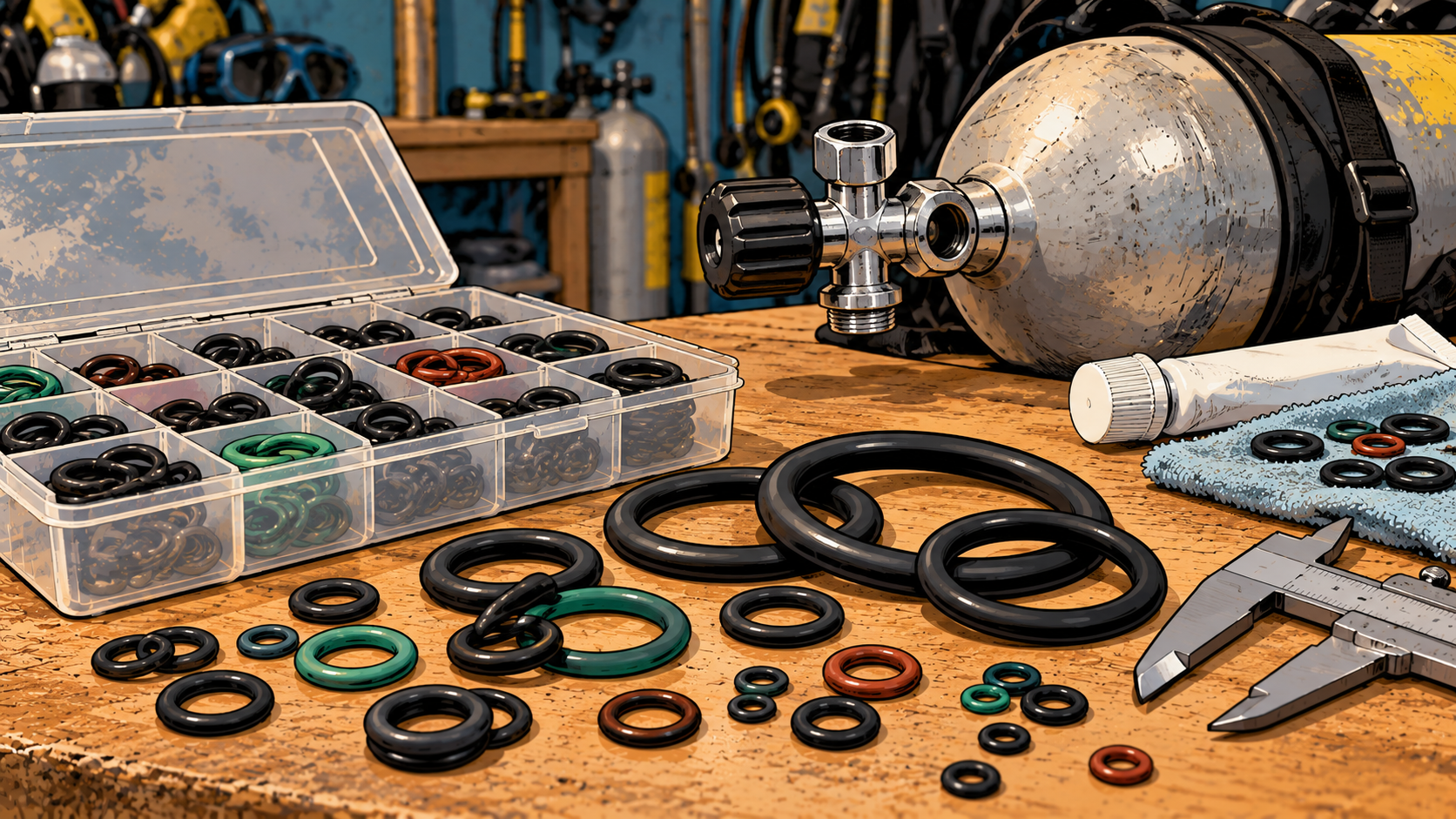
The seal must also fit the construction precisely. For parallel neck threads, an O-ring is often used, but not every O-ring of approximately the right size is suitable. The material, hardness, cross-section, and placement must match the technical specifications. An O-ring that is damaged during assembly or incorrectly seated in its groove can cause leakage when filling. Therefore, during professional maintenance, not only the thread and valve are inspected but also the sealing surfaces and the prescribed seals.
Ultimately, this chapter shows how important standardization is in high-pressure equipment. A thread may seem like a simple mechanical part, but behind the designations M25×2, NPSM, and BSPP lie precisely defined dimensions, thread profiles, and assembly instructions. The difference between a safe and a dangerous connection can literally be less than a millimeter. For diving professionals, the most important lesson is therefore not that they must know every thread from memory, but that they should never assume two parts belong together simply because they appear to fit.
And that brings us to another part that is at least as small, but bears at least as much responsibility: the seal. Because even when the threads perfectly match and the valve is correctly assembled, the compressed air must still remain inside the cylinder. For that, we rely on small rubber rings, precisely designed sealing surfaces, and sometimes also on a special pressure relief device intended to burst open in cases of extreme overpressure. The next chapter will discuss O-rings, burst disks, and the other small components that keep a high-pressure system safe.
5. Small Parts, Big Responsibility
We have now seen how much pressure a dive cylinder can withstand, what information is on the shoulder, and why the connection between the cylinder and valve must meet precise technical requirements. But even if the cylinder is perfectly manufactured, the threading matches exactly, and the valve is correctly mounted, we are not done yet. After all, the compressed air must actually stay inside the cylinder. For that, we rely on parts so small that most divers hardly give them any thought. A rubber ring just a few millimeters wide, a precisely finished metal sealing surface, or a thin membrane that must rupture at extreme overpressure — these are not impressive parts, but they fulfill a particularly important function.
This is perhaps one of the most remarkable features of high-pressure technology. The large, heavy components attract all the attention, while the reliability of the entire system sometimes depends on a seal barely larger than a coin. A dive cylinder can withstand hundreds of bar, but if an O-ring is missing or damaged, that same cylinder can lose its contents in a short time. Strength and gas tightness are two distinct properties. The first prevents structural failure; the second ensures the gas remains where it belongs.
The O-ring: a simple but particularly effective seal
The best-known seal in the diving world is undoubtedly the O-ring. The name simply refers to its shape: a ring with a circular cross-section, usually made of an elastic rubber-like material. An O-ring is slightly compressed between two designed surfaces, creating a gas-tight connection. In many high-pressure connections, the gas pressure also helps press the ring more firmly against the sealing surface. This simple principle makes the O-ring a particularly effective seal, even at pressures of hundreds of bar.
In a dive cylinder, O-rings are found in various places. At an INT connection, the familiar small O-ring sits in the opening of the cylinder valve, while for a DIN connection it is usually located on the regulator’s connection. Many parallel threading connections also use an O-ring between the valve and the cylinder neck. Additionally, the valve itself contains several seals that prevent gas from escaping along moving parts.
Not every O-ring is suitable for every application. The diameter, cross-section, hardness, and material must fit the design of the connection and the conditions in which it is used. The condition of the metal sealing surfaces is also important: scratches, corrosion, or dirt can cause leaks, even with a new O-ring. Behind this seemingly simple rubber ring lies surprisingly much technology. Those interested can find more information in our detailed article O-ring: a small journey around the world.
The burst disk: a safety device that must fail
Besides parts that keep the pressure inside, there are also components designed to open at a certain overpressure. The best-known example is the burst disk, also called rupture disk or, in Dutch, breekplaat. The English "rupture" comes from the Latin "rumpere," meaning to break or tear open. The name describes exactly what the part should do: fail at a predetermined pressure to help prevent a more dangerous pressure buildup.
Many North American dive cylinder valves contain a small metal burst disk in a specially designed holder. When the pressure inside the cylinder exceeds a certain limit, the membrane bursts open, allowing the compressed air to escape through a designated opening. The goal is to prevent extreme overpressure from ultimately causing the cylinder itself to fail. A burst disk is a form of overpressure protection, though it does not protect against all possible causes of a cylinder rupture.
The nominal burst pressure must match the cylinder and applicable regulations. Many common American aluminum dive cylinders with a working pressure of 3,000 psi (about 207 bar) use burst disk designs rated near 5,000 psi (about 345 bar). This is close to the hydrostatic test pressure of such cylinders. The exact design and allowed pressure values depend on the specifications of the cylinder and valve. Therefore, a burst disk must not be replaced simply by one with the same dimensions by chance.
It is notable that European diving cylinder valves are generally not equipped with such a burst disk. In North America, overpressure safety devices are prescribed for many common cylinder configurations, whereas the European approach for portable breathing air cylinders is often different. This difference also has a practical background. A burst disk can serve as an important safety device during extreme overpressure; however, if it unexpectedly ruptures during a dive, the diver can lose their breathing gas quickly. A device that provides protection against dangerous overpressure at the surface can thus itself pose a serious problem underwater.
That is not to say that one system is unequivocally safer than the other. Risks are managed differently within various technical and regulatory systems. For a European cylinder without a burst disk, safety must be ensured among other methods through design, pressure classification, prescribed inspections, and correct filling. For a North American cylinder with a burst disk, the requirements for overpressure protection are added. In both cases, the starting point remains the same: a diving cylinder must not be used above the pressure allowed for it.
Moreover, a burst disk is neither an ordinary pressure regulator nor a device for a filling station to check the maximum fill pressure. It is intended as the last safeguard against certain extreme overpressure situations. When a burst disk ruptures, it is accompanied by a powerful release of gas. Depending on the design and the amount of stored air, the cylinder can become largely or completely depressurized in a short time. This is not something that should happen during normal use, and certainly not an event to be regarded as a successful overfill protection method.
For an employee of a filling station, it is particularly important that the burst disk, if present, is part of the approved valve assembly. A missing, damaged, or incorrectly specified burst disk can compromise the safety of the system. Also, a leaking burst disk assembly must not be repaired with arbitrary parts or by disabling the safety device. Such work should be done by a qualified technician who has the appropriate parts and documentation.
The Cylinder Valve is More Than an On-Off Button
So far, we have mainly viewed the cylinder valve as the connection between the cylinder and the regulator, but inside the valve are various parts that must work carefully together. When you turn the knob, a mechanism moves to open or close the passage for compressed air. Internal seals must continue to function reliably both when the valve is fully open and when it is closed.
The exact construction differs by manufacturer and valve type. Some valves use a conventional valve seat pressed against a sealing surface, others have different mechanisms or additional features. Certain models also include check valves or residual pressure devices. These can, for example, help prevent a cylinder from becoming completely depressurized or make it harder for moisture and contamination to enter. But such features are not universal and their operation depends on the specific design.
The valve knob itself also warrants attention. A knob that turns stiffly, has unusually much play, or does not seal properly can indicate wear, contamination, or an internal defect. A valve that can only be opened or closed with great force should not be considered normal. The same applies to a valve that leaks after being correctly closed. The solution is not to turn the knob tighter and tighter, but to have the cause investigated. Precisely because a cylinder valve is used so often, it is tempting to treat small irregularities as unimportant. However, a reliable high-pressure system does not consist of parts that we hope will just hold out a little longer.
A special responsibility rests with dive centers and filling stations that manage large numbers of cylinders. Valves there are opened and closed daily, regulators and filling hoses connected and disconnected constantly, and O-rings replaced regularly. Small problems can easily become routine. A valve that hisses a little, an O-ring that leaks repeatedly, or a connection that does not run smoothly may sometimes be treated as an unavoidable annoyance. But precisely in a professional environment, such irregularities should be grounds to inspect the particular cylinder or valve more closely.
It helps to distinguish between tasks that a diving professional can safely perform and maintenance that should be left to a specialized technician. An instructor or Divemaster should be able to recognize a missing or damaged O-ring on the valve and replace it. They should also spot visible damage to the valve and know when a cylinder must not be used or filled. However, disassembling a cylinder valve, replacing internal parts, or adjusting an overpressure valve require specific knowledge, proper tools, and following the manufacturer's instructions.
The same applies to staff at a filling station. Their main responsibility is not to fix every defect on the spot but to prevent an unsafe cylinder from being filled. This requires technical knowledge, a consistent routine, and the willingness to reject a cylinder if something is wrong. A cylinder that makes an unusual noise, shows visible leakage, or whose valve does not function reliably must be inspected first. The fact that the same cylinder was filled without problems yesterday is not proof it is safe today.
Ultimately, it is often the smallest parts that remind us how precise high-pressure technology is. An O-ring just a few millimeters in size, a properly finished sealing surface, and a carefully designed valve mechanism make it possible to safely store thousands of liters of compressed air and use it in a controlled way. They may be less impressive than a thick steel cylinder or a shiny aluminum tank, but without these parts even the strongest diving cylinder would be barely useful.
6. Why Don’t All Diving Cylinders Speak the Same Language?
Imagine if every mobile phone manufacturer used its own charging plug. A Samsung cable wouldn’t fit an Apple phone, and a device from Japan would need a different plug again. Not so long ago, this was largely the reality. Now USB-C has become an almost universal connector for modern smartphones and many other electronic devices. We find it quite normal nowadays that competing manufacturers use the same connection.
In the diving world, it’s different. European, American, and British diving cylinders can have different thread standards for the connection between the cylinder and the valve. These differences are not just inconvenient: some threads look so similar that the wrong combination initially seems to fit, while the connection can fail under high pressure. Why have we succeeded in largely standardizing the phone connector, but still use different systems for diving cylinders?
In previous chapters, we have seen various examples. European diving cylinders are usually indicated in liters and bar, while American cylinders are often sold in cubic feet and show working pressure in psi. We use DIN and INT connections for regulators, different inspection systems for pressure vessels, and multiple thread standards to attach valves to cylinders. Some differences are just inconvenient. Others can become life-threatening if parts are mixed up.
This raises an interesting question. Why, after more than a century of international trade and industrial collaboration, have we still not managed to use the same technical standards worldwide? And perhaps more importantly: would the diving world really become safer if tomorrow we decided to abolish all differing systems?
The Historical Origin of Different Standards
To understand why so many different standards exist, we must go back to the Industrial Revolution. In the eighteenth and nineteenth centuries, machines became increasingly complex and there was a need for parts that could be produced independently. A bolt from one factory had to fit a nut from another factory. That sounds obvious today, but it wasn’t for a long time. Manufacturers used their own dimensions and thread profiles, so parts often had to be specially made for one machine.
An important step was made by the British engineer Joseph Whitworth. In 1841, he presented a proposal for a uniform thread standard, with fixed ratios between diameter, thread pitch, and thread profile. His system made it possible to reliably combine bolts and nuts from different manufacturers. The Whitworth thread was widely used in Great Britain and later also formed the basis for several British thread standards.
But the British industry was not the only one that needed uniform dimensions. In the United States, their own thread standards developed based on inch sizes, while on the European continent the metric system gained increasing influence. Remarkably, all these standards originally tried to solve the same problem: reducing confusion, making production cheaper, and making parts interchangeable. Within their own industrial environments, they often worked excellently. The problem only arose when these different systems began to meet on the international market.
Nowadays, many technical standards are internationally harmonized, but existing standards do not simply disappear. Factories have arranged their machines and tools accordingly, producers have made millions of parts according to those specifications, and users have equipment that sometimes lasts for decades. Replacing a standard means much more than agreeing on a new dimension. It also means that an enormous amount of existing equipment no longer naturally fits what is produced afterward.
That explains why we still encounter different neck thread standards on diving cylinders. Modern European cylinders usually use the metric M25×2 thread, while American cylinders commonly use the ¾-14 NPSM standard. Additionally, we still find older cylinders with the British G¾ thread (BSPP). Although Europe, including Great Britain, largely switched to metric neck threads in the 1990s, many of those older cylinders are still in use. The British standard has thus largely disappeared from new production but not from the diving world. And as long as different systems exist side by side, the risk remains that parts are interchanged which at first glance appear to fit but are technically incompatible.
When a Wrong Thread Can Cost Lives
Some technical differences between various standards are so small that they are hardly recognizable without suitable measuring tools. This makes these connections particularly treacherous. When two parts clearly do not fit, the chance of a mistake is relatively small. But when a valve can be screwed a few turns into the wrong cylinder neck, it can falsely give the impression that the parts belong together.
The British Health and Safety Executive (HSE), the government agency for occupational safety, has been warning about this phenomenon for years. Some incompatible threads can be screwed so far together that the connection seems secure. A wrongly mounted valve can even withstand multiple filling cycles before the thread finally fails. When that happens, the valve can be shot out by the enormous force of the compressed air from the cylinder. The fact that a diving cylinder has been used for years without problems therefore does not prove that the valve is correctly mounted.
A serious accident was reported in December 2014 by the International Marine Contractors Association (IMCA). Onboard a ship deployed for professional diving operations, five professional divers were preparing for a dive when suddenly the valve shot out from an emergency air cylinder. The cylinder was under a pressure of about 180 bar. All five divers were injured. Technical assessment revealed that the valve's thread did not match that of the cylinder. The exact place and date of the accident were not disclosed. IMCA issued an official safety warning and emphasized the importance of careful checking of compatibility between cylinders and valves.
Almost a year later, on November 9, 2015, a similar accident occurred in the Australian state of Western Australia. An experienced service technician was filling a diving cylinder when the cylinder valve suddenly shot out of the bottle with enormous force. The valve, which was still connected to the filling bracket and filling hose, struck the employee in the face and caused life-threatening injuries. The filling station, pipelines, and ceiling were also severely damaged. Investigation revealed that on a cylinder with an American ¾-14 NPSM neck thread, a metric M25×2 valve had been mounted. The parts looked similar enough to be connected but were technically incompatible. Following the accident, the Australian workplace safety authority WorkSafe published an official warning.
Nearly seven years later, tragedy struck again. On Sunday morning, October 16, 2022, at the De Meerkamp swimming pool in Amstelveen, the Netherlands, another tragic accident took place. During an introductory dive of the local diving club, the valve suddenly shot out of a compressed air cylinder. The valve hit a dive instructor, who was so severely injured that he later died in the hospital that day. The pool was evacuated, and the Dutch Labour Inspectorate launched an investigation. Once again, the cause was a wrong combination of threaded connections: the cylinder had an internal G¾ thread, while the mounted valve had an external M25×2 thread. The valve was therefore slightly too small for the cylinder neck. Although the parts could be connected, the connection could not withstand the forces acting on it.
Four days after the accident, the Dutch Labour Inspectorate issued a safety warning for the diving industry. The repercussions extended further. On May 6, 2025, Dutch cylinder inspection companies collectively decided no longer to hydrostatically re-inspect diving cylinders with a G¾ neck thread. Even when such a cylinder is fitted with a properly matching G¾ valve, it will no longer be eligible for re-inspection with these companies. Not because the original combination is inherently unsafe, but due to the risk that someone might install an incorrect M25×2 valve on it in the future. Thus, an older, technically usable standard is being gradually removed from Dutch diving practice to prevent dangerous mix-ups.
What these accidents have in common is that the problem was not necessarily due to the strength of the cylinder or the quality of the valve. Both parts could independently meet their technical specifications, but together they did not form a safe connection. That might be the most important lesson: safety is not only a property of individual components, but also of the way these components are combined. And as long as different standards coexist, compatibility remains a responsibility that should never be assessed by eye alone.
Why old standards don’t just disappear
From a safety engineering perspective, it is effectively a system-level design flaw when two incompatible threads look so similar that they can be connected without much effort. After such serious accidents, the solution might seem straightforward: agree on one global thread standard and ban all others. If every diving cylinder and every valve had the same connection, mix-ups between different neck threads would no longer occur. However, reality is more complicated. Introducing a new standard is relatively simple; ensuring that all existing equipment complies with that standard is a completely different matter.
Diving cylinders have an exceptionally long lifespan. A well-maintained steel cylinder can last for decades, and many aluminum cylinders remain in use for a long time. Manufacturers continue to produce valves, spare parts, and other components for equipment that may no longer be sold new. Older thread standards therefore do not automatically disappear when manufacturers decide to use another. Even if worldwide agreement on a single unified neck thread were reached today, millions of cylinders with different fittings would remain in circulation for many years.
The European transition to M25×2 shows how this works in practice. Since the 1990s, this metric neck thread has gradually become the common standard for new European diving cylinders. Nevertheless, we still occasionally encounter older cylinders with the British G¾ thread. As long as properly fitting valves are available for them and the cylinders meet the applicable inspection requirements, such an older combination does not have to be technically unsafe. The danger mainly arises when someone switches parts from different systems. An old standard is therefore not necessarily a bad standard, but the coexistence of different standards makes mistakes possible.
An immediate worldwide switch would also have enormous economic and practical consequences. Dive centers, filling stations, and individual divers would have to replace existing cylinders, many of which could still be safely used for years. Manufacturers would have to adapt their production, and inspection companies would need to implement new procedures. Moreover, a large amount of material would be prematurely discarded. From a sustainability perspective, that is hard to justify, especially when it involves sturdy metal pressure holders whose production requires significant amounts of raw materials and energy.
But a gradual transition has its own risks. During the transition period, old and new systems coexist. As older cylinders become rarer, familiarity with their technical specifications may also decrease. A young service technician who works almost exclusively with M25×2 may not immediately recognize an older G¾ cylinder. At the same time, original replacement valves may become harder to obtain, creating the temptation to use a part that looks approximately the same. Precisely in the final phase of a transition, an outdated standard may therefore require extra attention.
The Dutch decision from 2025 to no longer hydrostatically re-inspect G¾ cylinders is an example of another approach. Instead of relying solely on correct identification and assembly, there is an attempt to gradually reduce the number of cylinders with this older connection. This reduces the chance of mix-ups in the long term but also means that cylinders that may still be technically sound are taken out of use earlier. It is a trade-off between preserving existing equipment and reducing a safety risk that has had serious consequences in practice.
This makes clear that international standardization is not just a technical issue. The dimensions of a thread can be precisely defined, but the transition to a different standard also requires economic choices, regulations, training, and cooperation between manufacturers, inspection bodies, and users. A uniform connection can help prevent future mistakes, but as long as old and new equipment coexist, careful identification of each cylinder and each valve remains necessary. The question is therefore not only which standard is technically preferable, but also who ultimately decides which standard will be used worldwide.
The Americans and the Rest of the World
If international standardization offers so many advantages, why do American and European diving cylinders still use different neck threads? The answer has less to do with the technical quality of the threads and more with the history and organization of the industry. The United States has a large domestic market for pressure cylinders, with manufacturers that have produced according to American standards for decades. Meanwhile, Europe has developed its own standards and largely harmonized them. Both systems operate within their own markets, and manufacturers have little direct incentive to voluntarily replace a well-functioning production standard.
Regulations also play an important role. In the United States, transportable gas cylinders fall under the regulations of the Department of Transportation (DOT), while in Europe, among others, the European regulations for transportable pressure equipment and associated technical standards apply. These regulations go far beyond just the thread on the cylinder neck. They set requirements for the design, manufacture, testing, markings, and periodic inspections of cylinders. An American cylinder, as we saw earlier, is not simply a European cylinder with a different thread. Both are part of a larger system of technical regulations, certification, and oversight.
This does not mean, however, that the American and European industries work completely apart from each other. Through international organizations such as ISO (International Organization for Standardization), standards are developed to which experts and national standardization organizations from various countries contribute. There are also international standards for gas cylinders covering materials, design, testing, and connections, among other aspects. For example, ISO 11363-1 describes, among other things, different thread profiles for connections between gas cylinders and valves. International standardization therefore does not necessarily mean that only one design is allowed anymore. An international standard can also accurately describe multiple existing systems so that manufacturers and inspection bodies know the specifications that parts must meet.
That is simultaneously the strength and the limitation of international cooperation. Documenting existing differences makes the industry clearer and safer, but it does not automatically eliminate those differences. A standard that recognizes both metric and American connections helps to produce and inspect each connection correctly. But as long as both connections remain in use, there is also the possibility that someone might interchange them. The difference between standardizing individual systems and actually unifying those systems is thus more important than it appears at first glance.
The European transition to M25×2 shows that further harmonization is indeed possible. Various national traditions have largely made way for one common neck thread for new diving cylinders. A similar international agreement could eventually reduce the differences between the European and American markets. However, this would require cooperation not only among standardization organizations but also among cylinder manufacturers, valve producers, certification bodies, and regulatory authorities. Moreover, they would have to agree on a transition period long enough to responsibly continue using existing equipment, but clear enough to prevent old and new systems from endlessly coexisting.
The biggest obstacle may be that the individual manufacturers have little to gain as long as their own system functions well. The benefits of one worldwide connection would primarily be visible in the safety and simplicity of international diving practice. The costs of a switch, on the other hand, initially fall on the industry and the users who must adapt or replace their equipment. Ultimately, standardization thus also becomes a matter of shared responsibility: who is willing to invest today in a solution whose benefits will only be fully apparent decades from now?
One Global Standard: Ideal or Illusion?
Wouldn't it be much simpler if every diving cylinder in the world had the same neck thread? Then a valve from Europe would fit an American cylinder without problems, and a dive center in Curaçao would no longer need to wonder according to which standard a cylinder brought in was made. For an international activity like diving, that seems an obvious ideal. Divers travel the world over, diving equipment is traded internationally, and dive centers work daily with gear from various manufacturers. Why then continue to use different systems for a connection so important to safety?
Technically, there is little that makes worldwide standardization impossible. Both the European M25×2 and the American ¾-14 NPSM thread can, if correctly designed and applied, form a safe connection between cylinder and valve. It's not about which system is fundamentally better but about choosing one common design. This should also take into account smaller cylinders, which sometimes use other neck threads because of their size and applications. Complete uniformity for every conceivable gas cylinder may not be realistic, but further harmonization should certainly be possible for the large group of common diving cylinders.
The most important condition is that such a change takes place gradually and carefully. For example, an international agreement could determine that new diving cylinders from a certain date onwards are produced according to one agreed-upon standard, while existing cylinders may remain in use under clear conditions for their remaining service life. At the same time, manufacturers and inspection bodies should ensure unambiguous markings, reliable identification methods, and good information for everyone who installs cylinder valves or inspects cylinders. After all, the goal should be to reduce the number of possible mistakes, not to create new uncertainties during the transition.
Until then, a significant part of the responsibility lies with the people who work with diving cylinders daily. A cylinder valve should never be selected solely because it looks fitting or can be screwed in without much resistance. The thread of both the cylinder and the valve must be identified with certainty, and in case of doubt, the assembly should not proceed. This applies to manufacturers and specialized maintenance companies, but also to dive centers that use older cylinders. Precisely because the consequences of a wrong combination can be so serious, an inspection based on assumptions is insufficient.
Perhaps European and American diving cylinders will still have different neck threads in fifty years. Perhaps the industry will eventually manage to agree on one common standard. But history shows that technical standards do not automatically disappear once a better or simpler alternative becomes available. For that, international agreements, economic willingness, and above all the will to prioritize safety over familiarity with existing systems are necessary.
The diving cylinder itself has changed enormously over more than a century. Materials have improved, production methods refined, and inspection requirements further developed. Yet the safety of a modern cylinder can still depend on a thread whose origin dates back to industrial agreements from the nineteenth century. This is not necessarily wrong: old technology can function excellently. But when two different standards look so similar that a mistake becomes life-threatening, there is every reason to ask ourselves whether we really want to keep those differences forever.
A good standard ensures that parts fit together. An even better standard helps prevent parts that do NOT fit together from being connected anyway. But for now, a completely new, globally implemented neck thread is little more than a pipe dream. The existing systems are deeply entrenched in the industry, and the chance that Europe and the United States will jointly switch to a new standard in the short term seems small. Until then, we will therefore have to continue working with different threads, and above all make sure that we never mix them up.
And with that, we reach the end of the third part of Cylinderology. We began with the question of how much pressure a diving cylinder can withstand and ended with a much bigger question: how do we ensure that parts of globally used equipment can also be safely combined worldwide? Along the way, we have seen that safety depends not only on strong materials and precise manufacturing but also on clear markings, reliable seals, proper connections, and international agreements.
But even when all those matters are correctly arranged, a diving cylinder does not remain safe automatically. Cylinders are damaged, materials age, and moisture, salt, and corrosion can leave their marks over the years. Therefore, diving cylinders must be inspected and tested regularly. How this is done, what problems may emerge during inspection, and when a cylinder must ultimately be condemned, we will examine in the fourth and final part of this series.